5/19/2009
David noticed that the boat that holds the lights and cameras gets hot quickly, which we figured might happen. One way to cool it is to add a fan or two, to circulate the air so that it can be cooled by the end plugs which should be at water temperature.
Another way to do it could be to circulate water inside the SCULL, using tubing attached to the light mounting. This probably would require a pump, and could cause leaks, complication, etc. If the fan trick doesn't work, we might look into this. Liquid cooling is being used on fast computers by the gaming crowd, so the technology is around, but maybe it's a bit too large.
5/10/2009
Happy Mother's Day, Janet and Joan!
I mounted the forward thrusters and nozzles to the frame, with welded brackets. Here is the design process
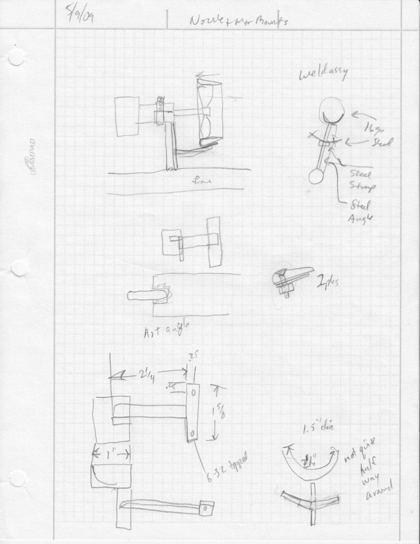
And the result of the thruster mounting, ready for some cable/connector testing

I've also been working on the calculations to figure out how big the bouyancy tanks need to be. It would be nice if they were not quite big enough, so we could add one more, and have petcocks on it so we can fill it partly full of water, to fine tune the bouyancy. Also we could put it where it needs to be to balance the robot front/rear/side.
5/9/2009
David has been working on the programming of the speed controllers. He also got some smaller glands for the connectors, and I will play with the wires from the motors to see if I can seal them. He got some heat shrink tubing with adhesive inside, and showed me a technique to have two wires enter one end of the tube, and seal the wires individually.
I worked on the tech report, and added mission strategy from Steve.
5/8/2009
We are working on the manipulator design, which has turned into a couple of aluminum rods, with plastic pieces sliding on it driven by a lead screw powered bya bilge pump motor, and a squeezing claw thingy that can open wide. We have most of the parts to make it for testing.
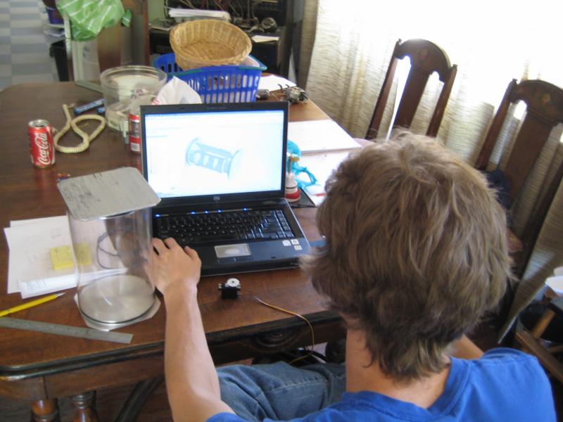
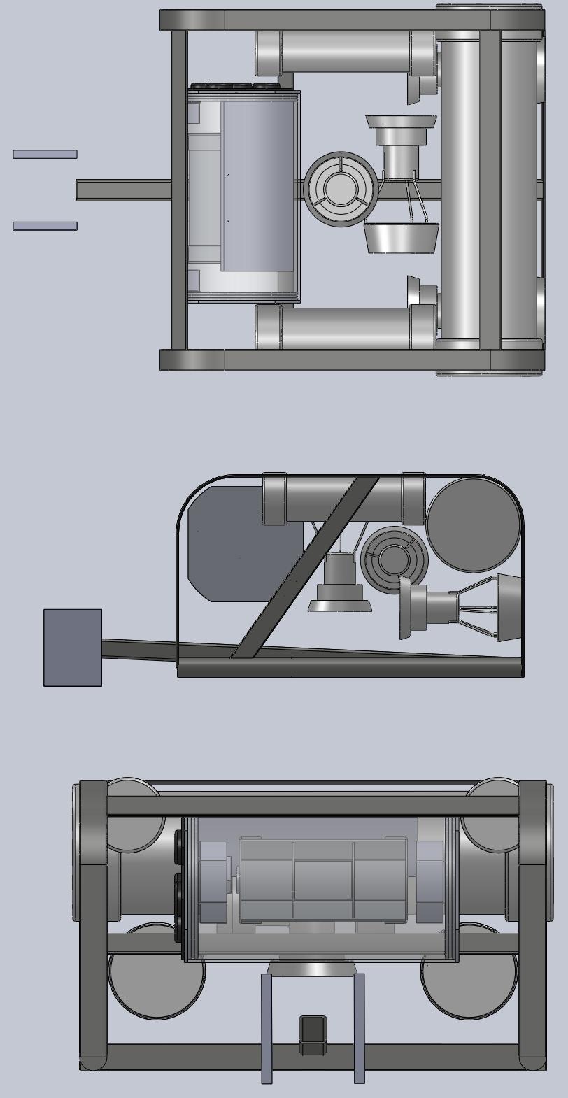
We also worked on revising the SolidWorks model of the robot, this is it so far
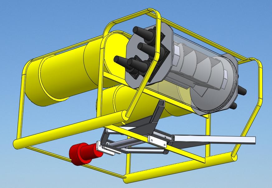
And we've been talking about 3D viewing, and ways we could make a cheap stereoscopic setup with stuff we have. We haven't come up with any feasible ideas yet.
We went basket shopping, and found this one at Target for $7, and a larger one that's more square for $10. With the two handles tied together, and some bouyancy, it might work for harvesting props.
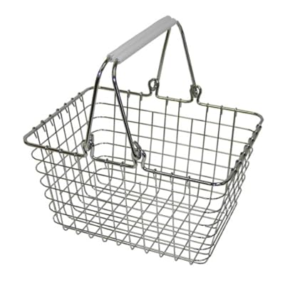
5/2/2009
This is the design sketch I've been working to for the frame, more or less.
5/1/2009
And an update from David on the electronics:
"The Bulgin connectors shipped from Digikey on Thursday via Priority Mail, so they ought to arrive Monday or Tuesday.
I'm working hard on the circuit board. I got the schematic and the basic component placement done except for the light bulb on/off switch and some connectors.
I also realized that providing the PWM servo output is no big deal, so I'll go ahead and do that. The logic required is just a few AND gates inside the CPLD chip.
We will need to make a little aluminum panel to attach to the end of the circuit board's mounting plate, to hold the Mini Fit Jr. connectors that take signals from the camera head and the removable end plug to the circuit boards. It will be about 2x4" and have about 5 rectangular holes to mount the connectors. I have a nibbling tool that makes short work of the rectangular holes.
The PC board is looking like it's 8" x 2.5" (plus two rows of flat TO-220 packages) but that could change."
4/30/2009
David did some report writing, concerning the motor driver circuitry, and the robot specifications. Further discussion led us to consider using the vEx signal splitter to interface the servo control. He will probably buy one and see how it works, although I already provided him with some photos of the insides of one.
4/26/2009
Steve has been working on the robot design some more, trying to get the bouyancy equal to the weight. It still has a ways to go, but this is the latest rendering:

David is also thinking about a way to gather data on the rov and send it up to the surface on an RS-232 serial cable, for display on a laptop. This might require us to get an old laptop working...we could do it in MS-DOS, or an older version of Windows. Fortunately I have several old laptops. There might be a simpler way to do it, though.
4/25/2009
Steve worked for a while on the design of the parts inside the enclosure, as well as the overall chassis. The program showed that the robot would weigh over 12kg, which is more than I expected. We discussed making it a bit smaller, and adding some more air chambers on the top, sides to help keep it afloat.
I brought a vEx transmitter to Tucson so David could play with it. We plan to use two of them to control the robot, one for the driving and the other for the camera and light. David has a design for the four channel motor controller partly done, and plans to prototype a single channel very soon to make sure it works as he expects. He has the prototype thruster and the bollard pull testing setup, to help evaluate it. We discussed the various other electronics that the robot might need, including power for the lights, pressure sensor (depth gage), thermometer, and a manipulator. He will work on an overall schematic, and decide how many of what pin count connectors will be needed, and order them soon so they can be installed in the enclosure.
Steve worked on the design some more and sent a rendering of the robot, with a mock up manipulator, and slightly shorter, with more floatation:
4/18/2009
David did some motor controller work:
"I worked on the NURC motor drive this evening. I brought a bucket of water into my workshop and put a bilge pump in it. Then I made a duty cycle controller using an IRFZ34 (.04 ohm, 55V N-channel MOSFET) driven by a square wave of variable duty cycle from an HP 3312A function generator.
The motor was run first at 12V and the duty cycle of the signal generator was seen to change the pump flow rate. Then I boosted the voltage to 24V and observed the operation.
I didn't get good results until I put a diode across the motor to short-circuit the motor current while the MOSFET is turned off. Without the diode, the motor current has to rise from zero on each pulse, so the motor only runs at a low switching frequency of less than 1 kHz. With the diode present, the motor current (and therefore speed) remains at the desired value independent of switching frequency.
When running the motor at 24V with the shorting diode in place, the motor pumps water at the nominal 12V rate when the switch duty cycle is near 50%, just as it should.
The diode's function will be implemented in the bidirectional motor controller (called an H bridge) by turning on the two MOSFETs in the bottom half of the H bridge which will short out the motor during the 'off' phase. This is standard procedure.
I have been thinking about our motor requirements, and decided that we may do just fine with a 36V system using 1/3 duty cycle for each of three motors: the two fore-aft and the up-down motor. The side-side motor is not going to be used for propulsion, so it won't need much power.
Changing the motor voltage is trivially easy if the system is designed for 48V, as long as I make the maximum duty cycle jumper-selectable in the motor controller.
To-do list:
1. Get a real motor with a prop and a thrust scale to make
quantitative analysis of motor controller ideas.
2. Run the above motor at 24, 36 and 48V to find any variation in
behavior or motor voltage problems.
3. Buy parts for and build a prototype motor speed controller that runs
on up to 48V input voltage.
PS Our Wal-Mart doesn't have a boating section. Boo hoo."
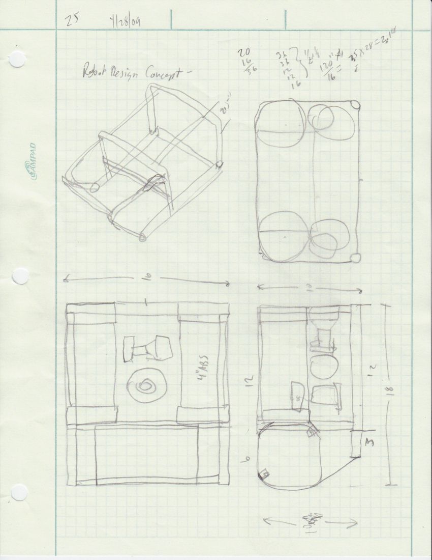
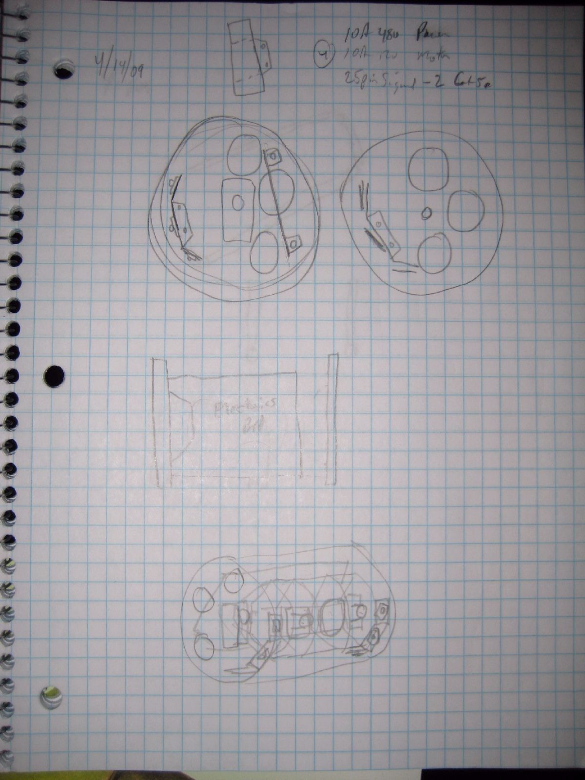
4/14/2009
Worked on the desing for the camera/light mounts in the electronics enclosure,came up with this....
 and
and
The part that holds the two cameras (with little lenses) and the halogen light, is made of sheet aluminum, and is mounted to a servo at one end, and pivots on a bolt at the other. The remaining electronic smount on a metal plate. The LEDs mount on plates mounted to each end cap.
4/11/2009
Met in Tucson today with David, Steve, and Janet, for about two hours. David's meeting notes follow.
Robot design meeting
April 11, 2009
Janet, Jim, Steven, David Forbes were present
Team name: The Typewriter Repairmen
Action items for NURC:
1) Register the team
2) Clarify solar charging rule - 20% below nominal voltage is bad for
SLAs.
Jim has done a lot of work figuring out what's important and designing a robot arrangement to do that stuff. We basically approved his ideas and discussed the control systems, lighting and cameras based on the requirements of the mission.
These are the specs as I recall them.
Robot: A steel strap frame with heavy steel bottom rails that holds a 6 inch dia, 1 foot long Lexan tube laterally at front-top for the cameras/electronics and a 4" dia, 1 foot long buoyancy tube laterally at rear-top. Buoyancy adjustment is done on the surface with a petcock valve.
Lexan tube: 1/8" wall, 6" dia, 12" long. Two 1/2" thick, turned aluminum end plugs with O-rings and flanges keep water out and provide mounting for electronics and heat sinking for hot things.
Motors: Four bilge pump motors with 3" dia. ducted props for up/down(1), forward/reverse/rotate(2) and sideways(1). Each motor has a bidirectional speed controller mounted in the tube that sucks on 48V.
Cameras: Two Radio Shack security cameras, probably with camcorder zoom lenses set to fixed wide-ish zoom setting with simple focus control for near/far work.
Camera mounting: The cameras and lights are mounted on a plate that can tilt up/down with motor control over a 45 degree range. Use an R/C servo with gear reduction to rotate the camera plate.
Lights: One or two 20 watt or so floods for distance driving, one or two 3W LEDs for close work, one 50W wide for search. The wide light may be floating on the surface.
Motor controllers: Each motor controller has a PWM input that commands speed and direction in a non-linear way so that:
0% PWM is full reverse
25% PWM is 10 reverse
50% PWM is stopped
25% PWM is 10 forward
100% PWM is full forward
Batteries: On the surface, four 12V 12AH AGM sealed lead-acid wired in series to make 48V. A 15 amp fuse protects the batteries from the robot.
Solar charger: David has a 75W solar panel that will be used to charge the four batteries in parallel during the daytime event. This requires some clarification of the rules, as they state that the batteries must be discharged to 20% below their nominal voltage, which is forbidden by the battery data sheets.
Tether: Two Ethernet cables and one zip cord, braided 4" per twist. The signals on the two Ethernet cables are:
1 pr clean 12V power? (or a small 6V 1.2AH battery in the Lexan
tube)
1 pr pwm motor command
1 pr pwm camera command
1 pr manipulator command
2 pr video return
1 pr audio return
1 pr telemetry return, RS-232 serial?
Motor control panel: A joystick with twist for forward/reverse/sideways/rotate plus a lever for up/down.
Camera/manipulator control panel: Camera focus knob or lever, camera tilt up/down lever, lighting switches, manipulator hook/release (?).
Telemetry: Pressure gage with 3 digit readout, audio recorder and output signal, two NTSC video outputs, temperature probe (thermistor?) with 3 digit readout.
4/10/2009
Not much got done during the FIRST robot competitions, and the preparations for going to Atlanta, after winning the AZ regional. I did work on some general design ideas before the previous post, but didn't mention it yet.
This drawing from March 11th or so is just refinement of some previous ideas, and some ideas for the size of the robot, and construction ideas.
Moving along to April, some thinking about the requirements, and how they might affect some of the design parameters. Main concerns are the size and weight of the robot, and the speed, power, and directional control of the propulsion system. Most tasks require high maneuverability, and there are a lot of tasks to be performed in a limited time, so speed is important. Some tasks require manipulating objects. Best guess is that a medium sized robot would be best, as it has enough mass to manipulate stuff, reasonable inertia for stability, but low enough that it would be highly maneuverable. The propulsion system requires power, speed, and fine control.
The tunnel limits the maximum size of the robot, and requires power and good maneuverability, and has high point value.
Considering a propulsion system with a fast/powerful front-rear thruster on each side, which drive the robot forward and backward, and can be driven differentially to rotate the robot, plus a powerful vertical thruster, and a single sideways directed thruster of lower speed/power, but with fine control for manipulating objects.
The robot mass might be between three and ten kilograms.
3/7/2009
Got a camera today, at Radio Shack, they have a sale on the $60 security camera for half off. It looks like it might be useable in an ROV. It has a kind of wide field of view, combined with a narrow beam IR illumination (which may not work too well under water). The color/bw switch seems to work ok, although I didn't play with it much at threshold conditions. Here are some pics of the inside of the camera.


I also picked up a 100 foot (30m) extension cable for it, it was 2/3 off so it cost $10. There might be enough wires on it to do more stuff, too. And it could work as a PS/2 keyboard or mouse extension cable if not. Also the camera comes with a 60 foot (20m) extension cable.
3/6/2009
Thinking about motors and wiring, if we have a box with electronics, and several motors connected to it, we'll need some way to connect them. Allied sells some IP68 connectors that are rated to 10m depth, not real expensive, field assemblable. Plug and socket.
An alternative to making thruster assemblies using motors and pipes and whatever is to use bilge pump motors. They come in a plastic housing, and are sealed to withstand about 10 m depth at the shaft seal. They come in a plastic housing, which needs to be partly cut away, and mounted with some sort of clamp. They are very commonly used on small DIY ROVs. Some examples from Rule. Cost is about $20 for the small ones, to around $100 for the 2000 gph models, and the larger ones are available in 24v.
On those connectors linked above, there are smaller ones available too, rated at 8 amps instead of 30, but they require soldering or crimping contacts, which should not be a big deal. Plug and socket. (although I'm not sure if these are mating connectors, I need to spend more time looking at the catalog)
On motors and props, it might be worthwhile to order a couple bilge pump motors and a few props, to do some Bollard thrust testing. Like an 1100 and a 1500 and 2, 2.5 and 3" props. I'll see if there's funding available.
Speed controllers...here are some pics of the small Banebots controllers. I'll see if I can figure out what the chip numbers are.
I could not figure out the chips, the numbers have been removed or somethign.
Another basic robot design idea, sort of modeled on the Seabotix smaller ROVs. A frame of some sort supports the thrusters, and the electronics unit. The electronics unit is made of a piece of big polycarbonate tube, perhaps 6" diameter by 6 to 10 inches long. It sits across the robot near the top, center. Each end of the tube is sealed with an O ring to an aluminum plate, perhaps 1/2" thick, with a groove for the O ring and tube machined into it. There are several long threaded rods or bolts holding the parts sandwiched together. A camera and light unit is mounted on a pivoting assembly that is controlled by a servo, so the vision system can be tilted from straight down, to horizontal or higher. Having the light and camera move together means there is less need for lights all over the robot. The camera will be able to see all around in the horizontal plane by robot movement. Thrust would be from two forward thrusters, one on each side, for fast movement forward, and turning ability. There would be a powerful vertical thruster in the center, and a small side thruster for "strafing" maneuvers. The electronics unit would also house the speed controller and whatever other sensory and drive stuff is needed. It could be pressurized if needed to take care of leaks. And it would be able to look at it's own "sump", so incoming water could be seen. Electrical connectors could be installed thru the endplate opposite the camera/light unit. The frame would need to be weighted at the bottom for stability, and the thrusters would need to be placed appropriately so the robot drives well. If they are clamped on, then changes could be made easily. There could be some extra bouyancy built into the top of the frame.

3/5/2009
Talked to David, and he sounds interested in working on the project, yeah! We discussed power, and speed control...he thinks we could make a 48v system with the battery on deck, and use a small power tether, with a switching power supply/speed controllers to drive the 12v motors. Also he has a 75w solar panel, which would be just right for charging the batteries. Would require a charging controller though.
Played with cameras and lights. My digital camera Canon SD1000 has a video output, and can be used as a camera for this if need be. Interesting. But we'll probably use a $90 board camera instead. With adequate light, it should be fine. A 20w halogen MR11 bulb might do the job.
Looked at the Seabotix robots, nice stuff, they seem to work. We might copy some of their ideas, but not all, since our budget and mfg abilities are pretty limited.
Thruster ideas... Might want to make simple thrusters. Max current draw of around 10 amps, normal about 5 amps. A motor like this might work good with direct drive, and a 2" or so diameter prop. Here is an idea for making the housing from iron pipe, which we can weld brackets to. I wonder if oil filling works ok with brushed motors like that? and if a simple packing would work to 15 ft depth?
3/4/2009
More ideas....which need to be sorted out...

Service vehicle: A sort of a boat, that will hold a lot of stuff, handle the ROV tether, provide overall lighting and birds eye view camera. It will be water resistant (not designed to be submerged more than a foot or two). It will be very bouyant. It can hold the main battery for the system. It need not have propulsion, as long as the ROV is capable of pulling it where it needs to go. It can control how much tether is extended to the ROV, so the ROV tether never need lay on the bottom.
Small, powerfull ROV: Minimum electronics on board, with a kind of fat tether. Powerful thrusters, powerful lights, good camera with tilt. Possibly a small secondary thrusting system for the manipulator end, possibly on the manipulator itself.
I played with the 50w track light some more. Last night, I put it in water, and it bubbled and fogged up. The lens is sealed to the reflector most of the way around with RTV, but there's a 1/8" gap. I dried it out and filled the gap in with RTV, let it set up, and tried the light in water again. This time the lens did not leak, but the seal at the back around the contacts bubbled, and the lens fogged again. I guess it's not a very well sealed lamp, and will need to be in a housing. There's another issue, which is that the beam width drops significantly in water. I did another experiment with a dome on the surface of the water, it seems to keep the beam width at it's normal size. So we could probably use the track lights in a housing with a dome, although it would be necessary to make sure that heat won't be a problem. Maybe using 39 watt or 20 watt lights would be better.
3/2/2009
Looks like we might be able to enter the 2009 NURC this June!
Mom made up a requirements spreadsheet for us, to help us figure out what we need to do, what we want to do, and help us decide which approach would work best.
We've been brainstorming some over the past few days, and discussing basic strategy. First we need to pick a name, and figure out who's on the team, and who's going to pay for all this, and how much they can afford.
Some parameters of the robot design, including what might be desirable to meet certain mission goals:
Maneuverability - Fine control, powerful (swim against current), fast
cruising speed, adjustable ballast boyancy system or powerful vertical
thruster
Vision - Light brightness and beam width, wide angle view for
navigating, close up (moveable?) view for manipulating props
Control - Full manual or automatic (microcontroller), switch speed
levels or variable control, holonomic drive or single motor control,
degrees of freedom (in 3 d environment)
Electronics - All inside the hull, or all separate, or combination,
battery location, lights separate
Robot configurations - separate mini ROV for exploration, or overall
navigation, boat/bouy with down camera/light for birds eye navigation
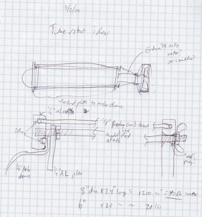
Some possible designs:

and some details of how to make a tube robot, using a 6 to 8 inch diameter polycarbonate tube, and aluminum plates at the ends, plus a polycarbonate dome for the camera.