6/10/2009
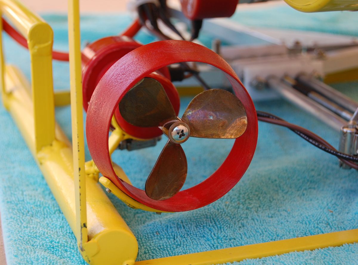
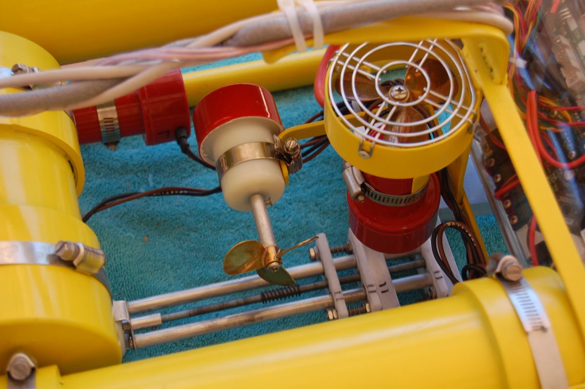
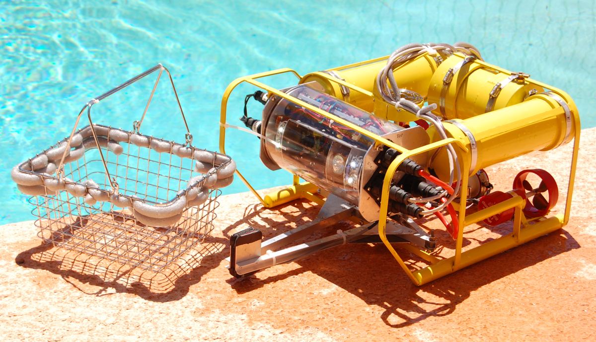
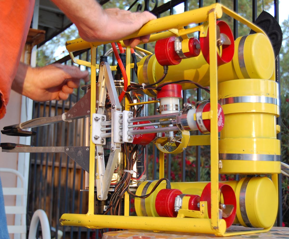
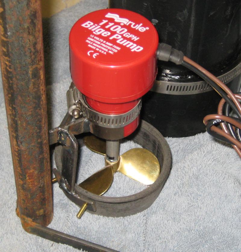
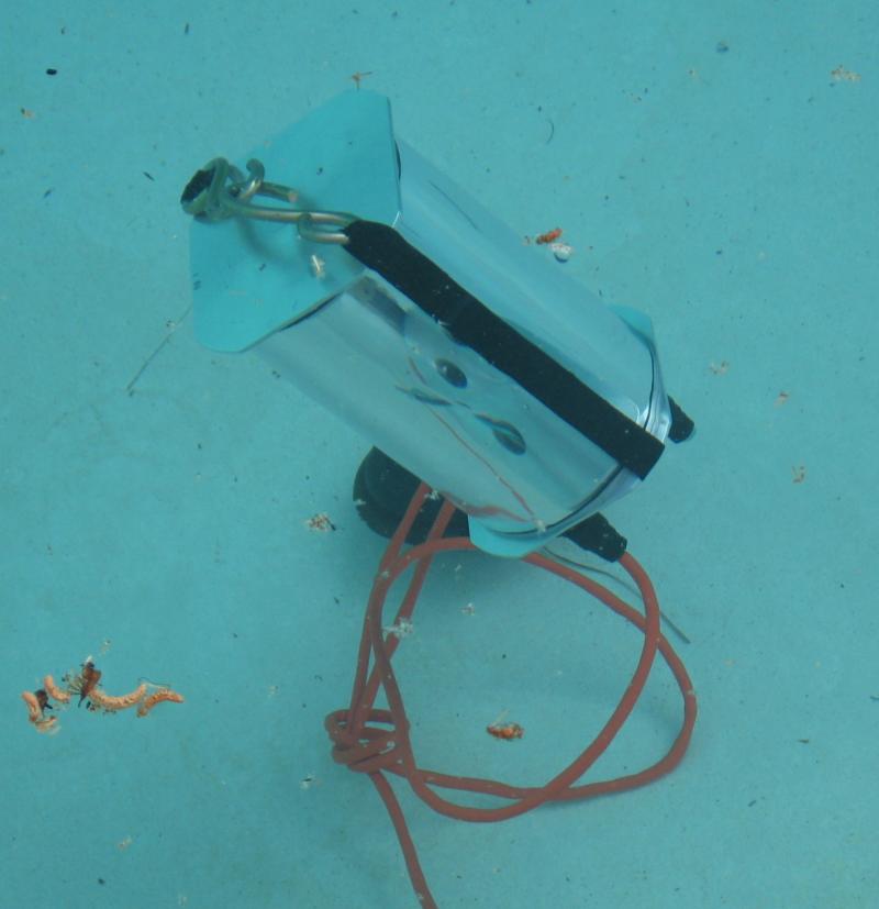
Steve has been noticing that we could use a bit more side thrust, so we built and installed a simple shroud, made of sheet aluiminum.
After our fun night in Tucson in a larger pool, we realized that
navigation might be a bit challenging. After some discussion and
shopping, we found the makings of our Magnetic Directional Indicator
system. Praise Velcro!
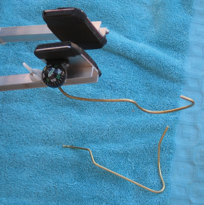
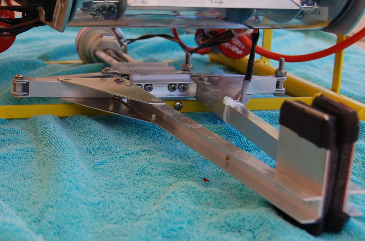
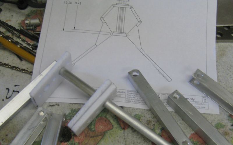
We also realized that there might be situations that require the use
of a hook or something instead of a grabber, so we made an
interchangeable tool holder. Shown not mounted is the lower
support for the science package, which likes to tilt downward without
it.
6/8/2009
David finished his write-up of the speed controller board design It's on his CathodeCorner web page.
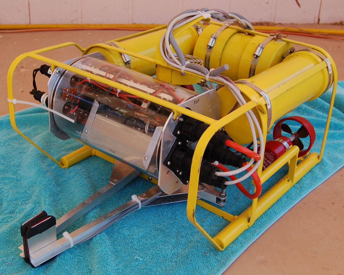
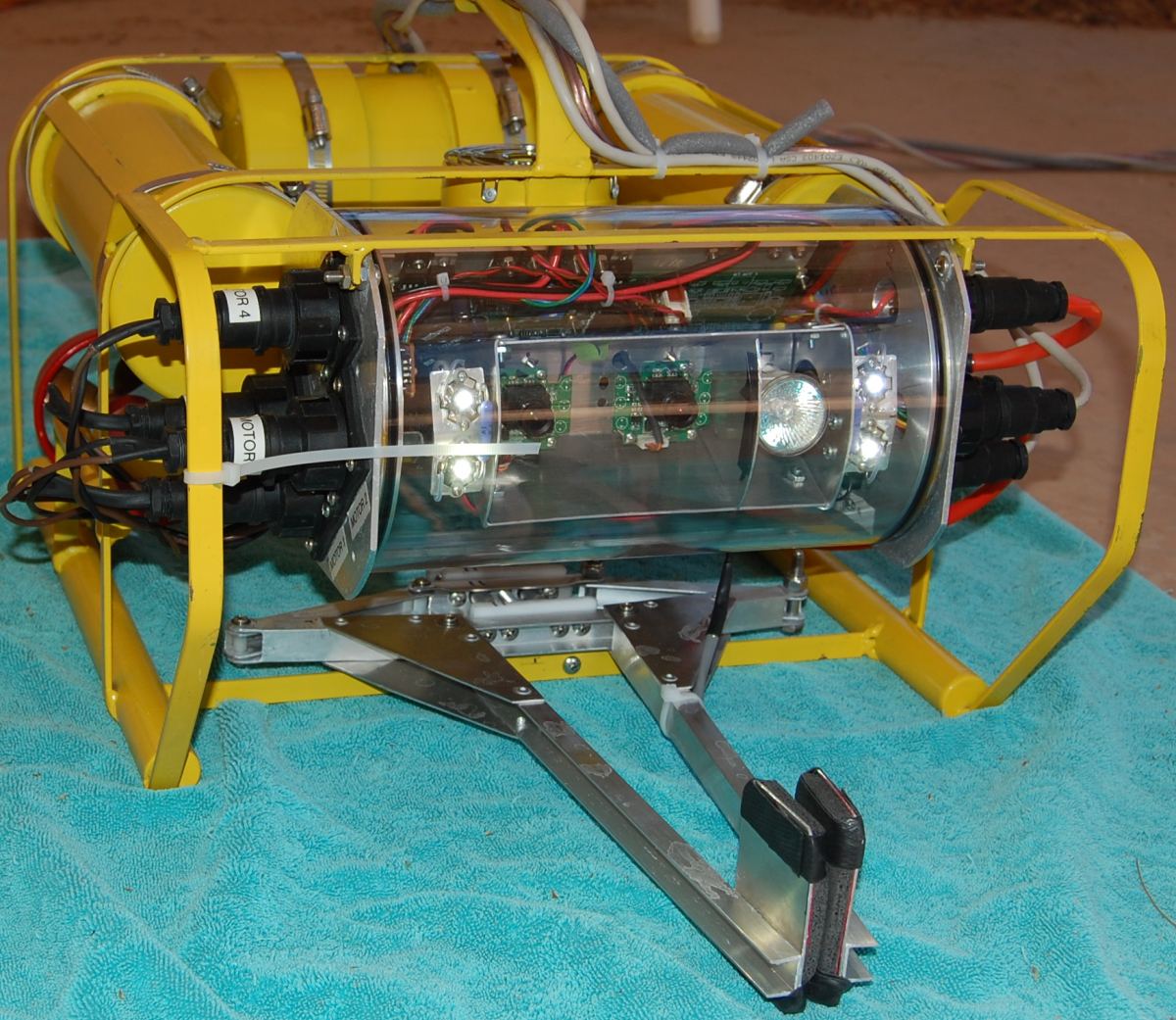
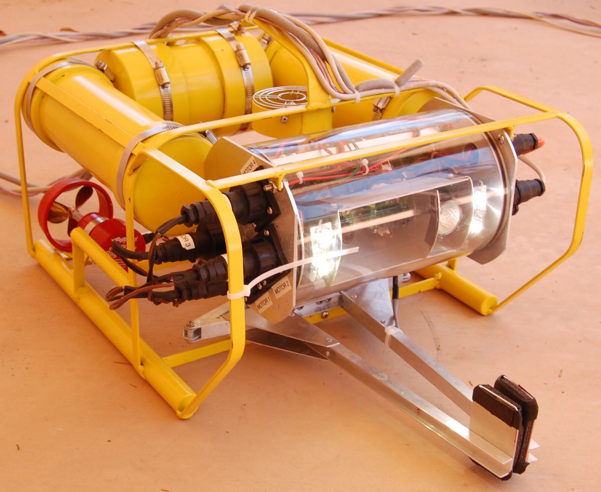
6/3/2009
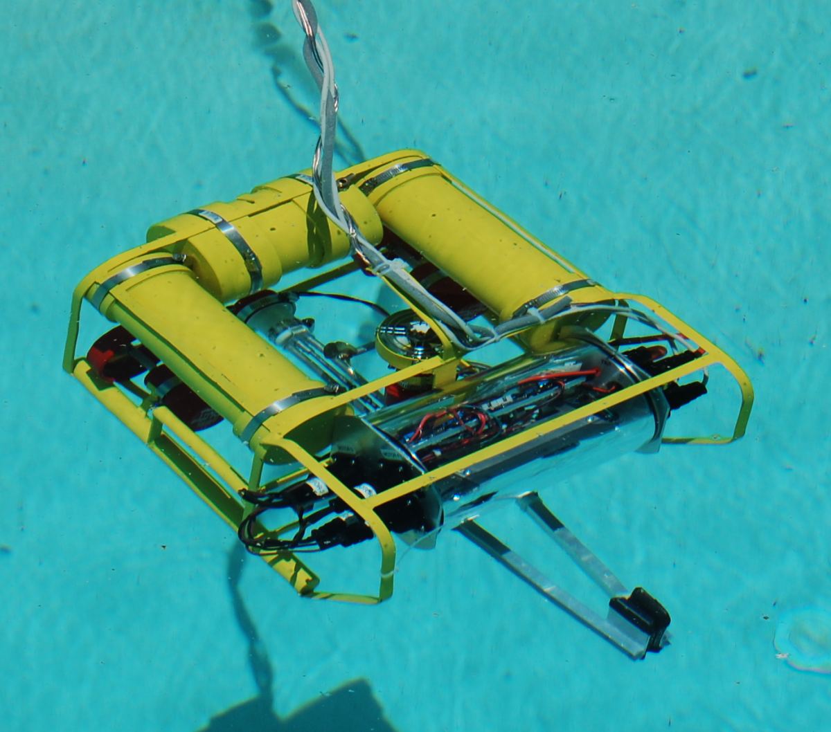
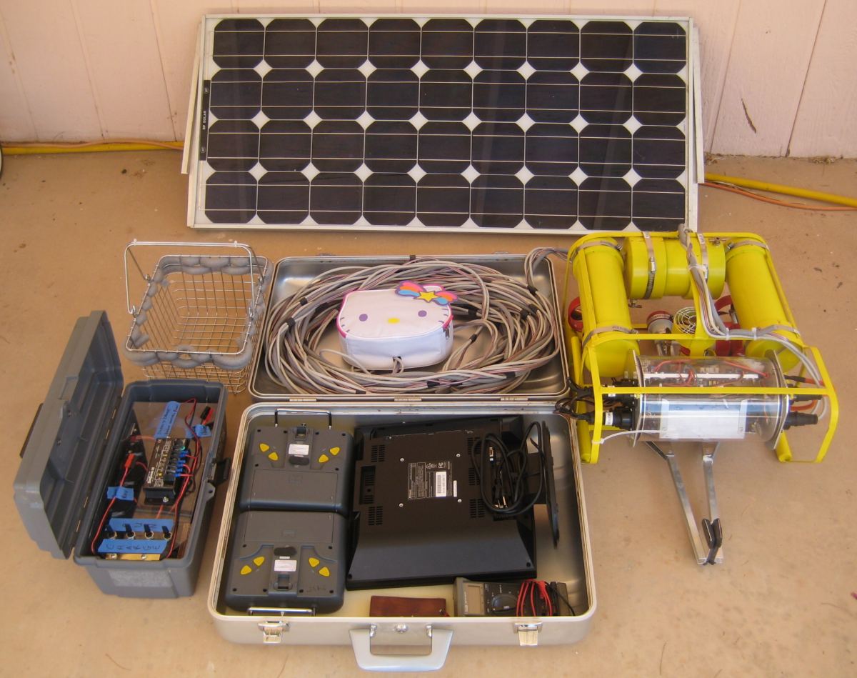
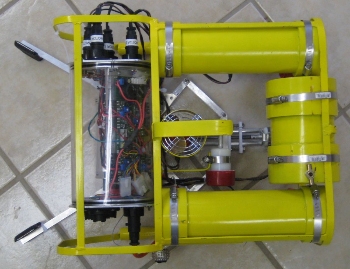
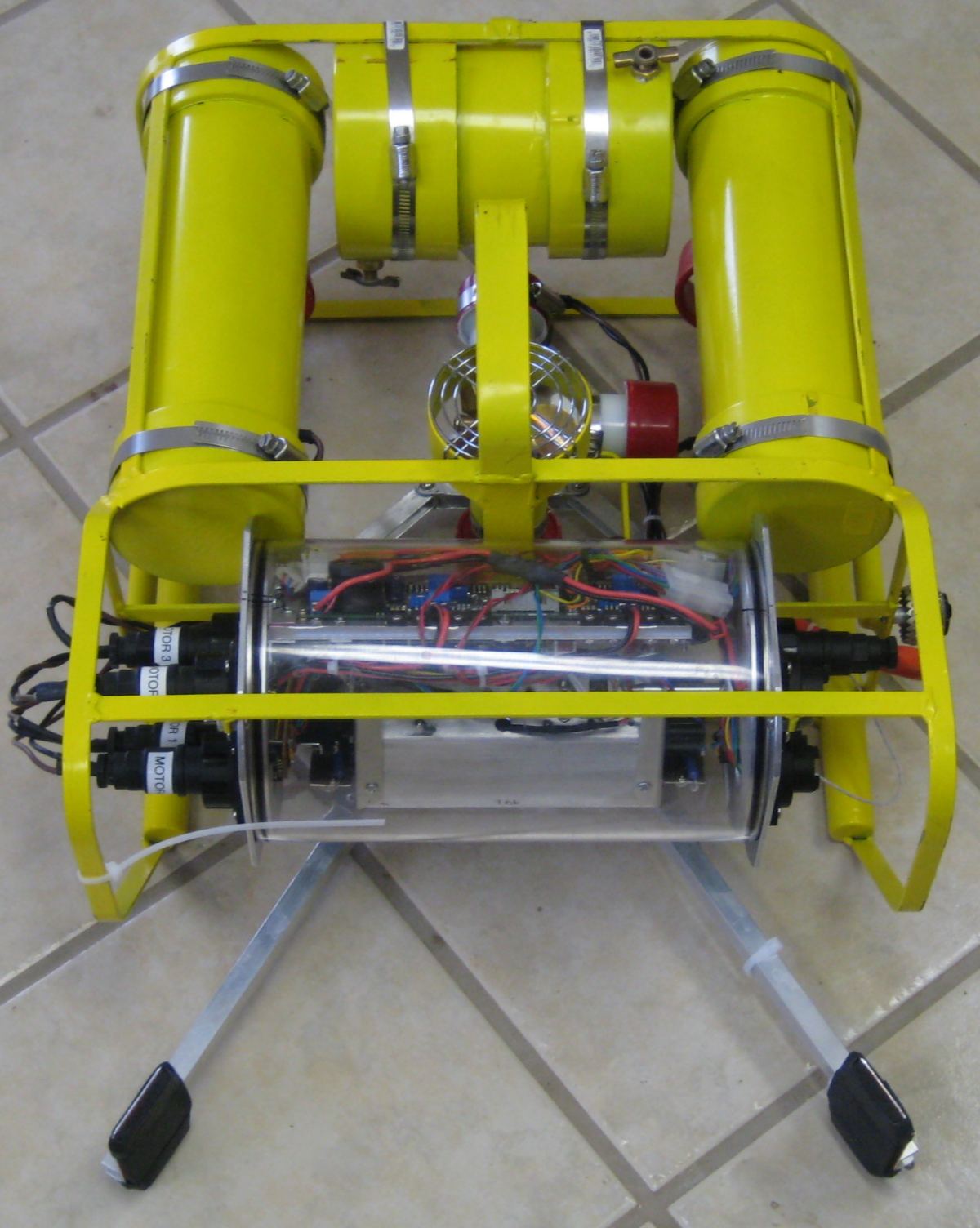
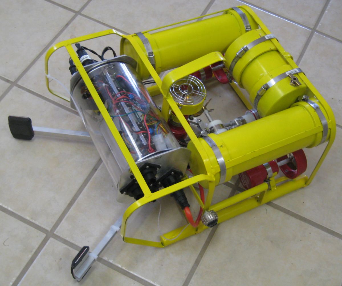
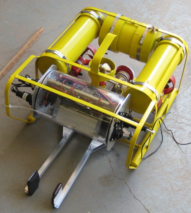
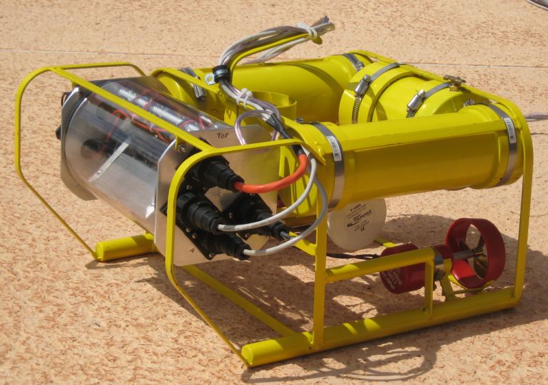
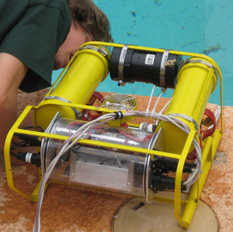
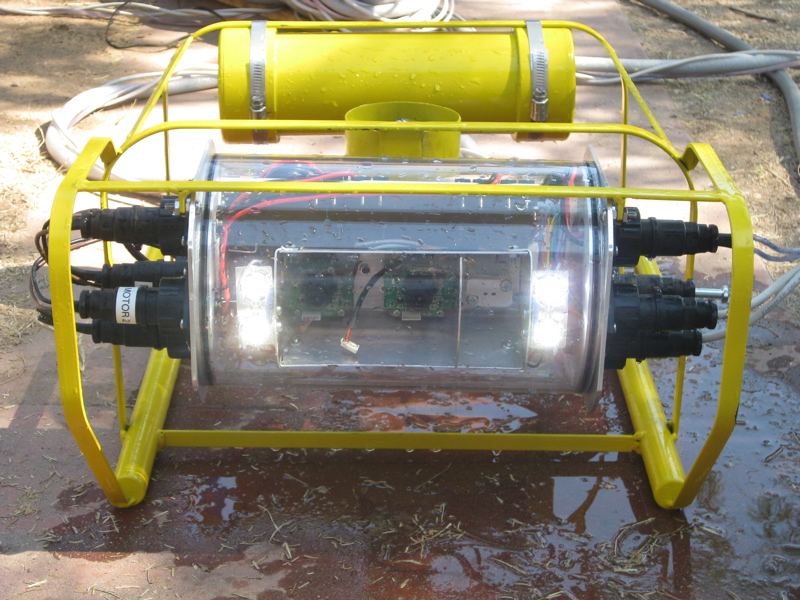
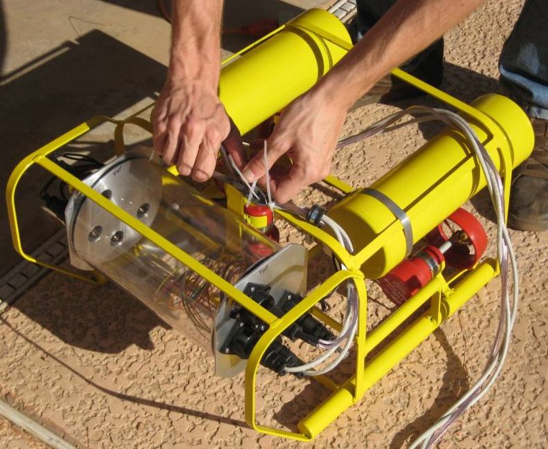
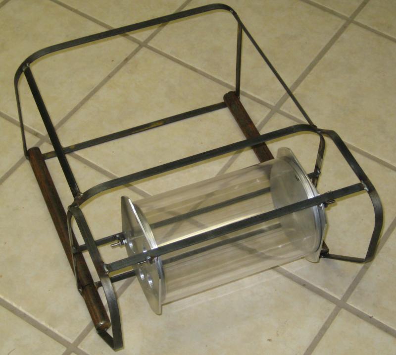
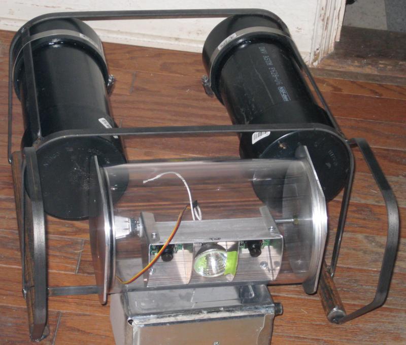
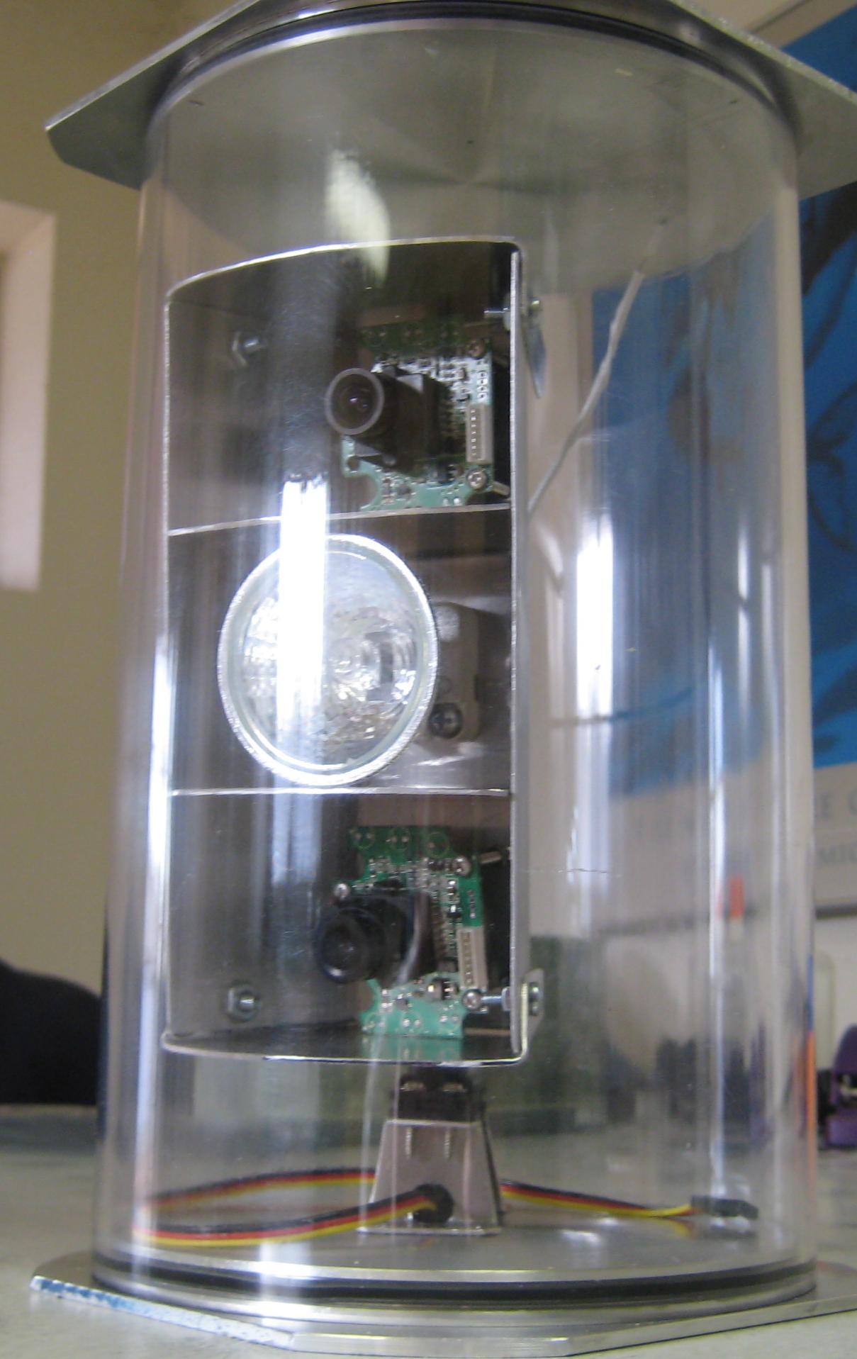
We seem to be about done building the robot. Here are some pictures of (mostly) finished Bob.

5/31/2009
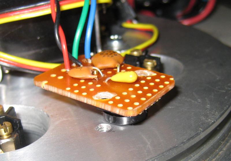
We got quite a bit done in the past few days. The temperature and pressure sensors are mounted on the ROV, the control system is encased in the new Hello Kitty Command Console, and the claw and side thruster motors have been replaced with Rule motors to match the other thrusters. First, the pressure sensor. It is a Freescale MPXA4250A pressure sensor that is designed to be used as a manifold pressure sensor in an automobile engine. It operates on five VDC and provides an analog voltage output proportional to absolute pressure, from 20 to 250 kPa, and since atmospheric pressure is about 100 kPa absolute and the water pressure at the bottom of the pool is about 150 kPa absolute, it's just right for our depth gage needs. Here it is mounted to a small breadboard with some noise filtering capacitors, on the end plug of the SCULL. The pressure sensor is the part between the breadboard and the aluminum plate. We drilled a small hole in the plate, and countersunk it to the outside diameter for a -005 O ring. Two O rings are placed on the protruding tube of the sensor, and it's pushed into the hole, and seals just fine.
We got a cheezy indoor/outdoor digital thermometer to use to measure temperature. It had a two meter wire with the outdoor temperature sensor (thermistor) on it, but we cut that off and attached it to a wire that connects to one of the connectors on the SCULL. This caused problems, because it did not seal well the first time, so we made up a new cable that is sealed with epoxy at the connector end, and it works fine now. The temperature calibration seems to be off, compared to a known accurate temperature meter, so we may want to do some more testing to make sure it will be sufficient.
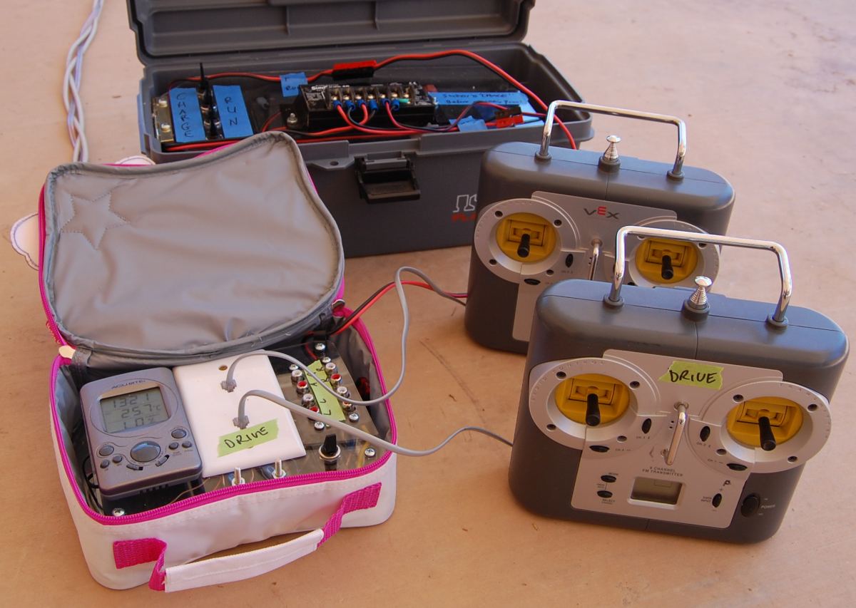
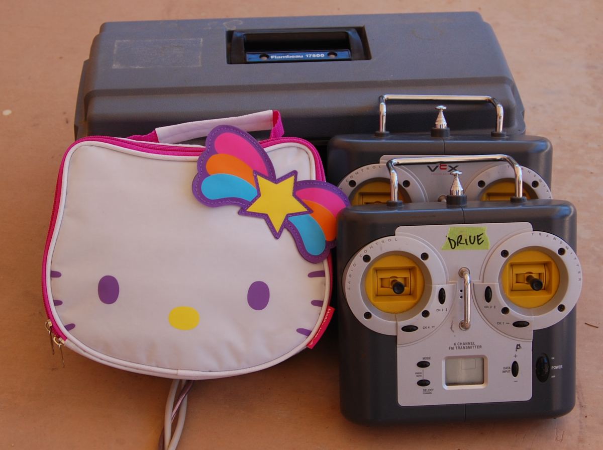
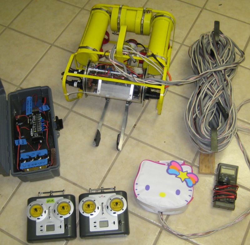
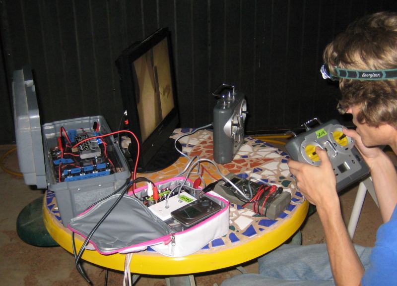
The control system was giving us trouble, we couldn't figure out how to get it into a nice case so that it is easily transported, connected, and safe while stored. We realized that we want the surface end of the tether to be terminated in a small box, so that it can be carried with the ROV with the tether attached to the ROV, or with the other control stuff in a case and disconnected from the ROV. The solution was to use a Hello Kitty soft side lunch box, with the wire connectors, power switch and fuse, thermometer, and whatnot inside. We made a panel to mount things to, a base plate to fit into the bottom of the lunch box, and wired it up.
The result is a collection of stuff that can be easily managed, and looks stylish too.
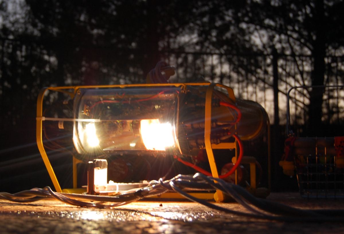
The control system is quick to set up, and works well. This is at night on the small table by the pool (the table is from the old McDonalds in town, which was the first drive-ithru McDonalds restaurant in the world)
5/28/2009
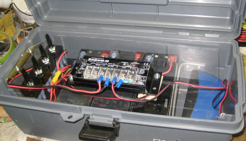
Not much progress, other things have been going on. We did figure out the battery storage system, which includes a tool box to hold the four batteries, four switches to select charge or run for each battery, mounting for the solar charging electronics, and wiring for recharging the vEx transmitter batteries from solar power.
We are also working on mounting the pressure sensor to measure depth. We need to find a temperature sensor and figure out how to wire it and mount the display.
5/23/2009
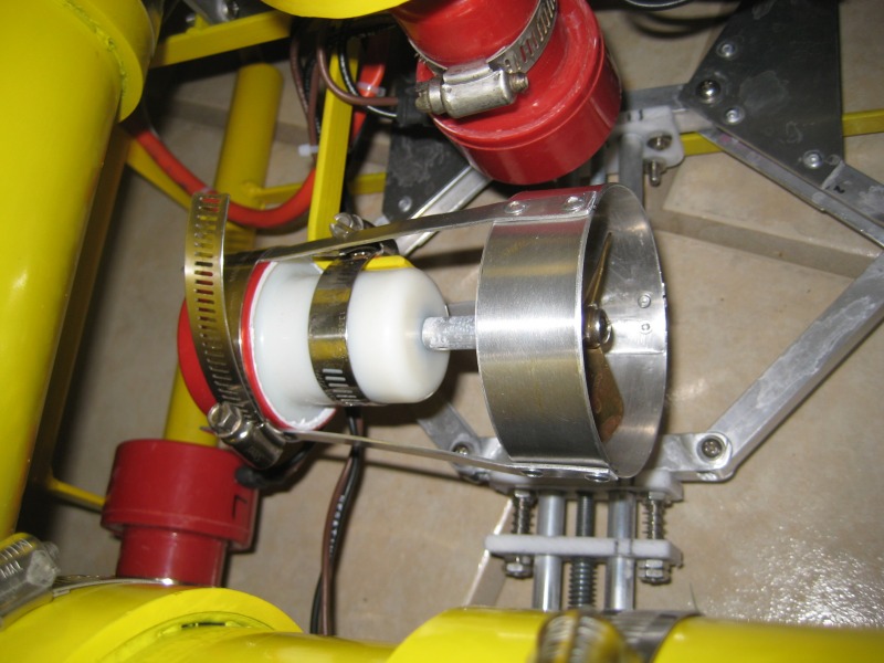
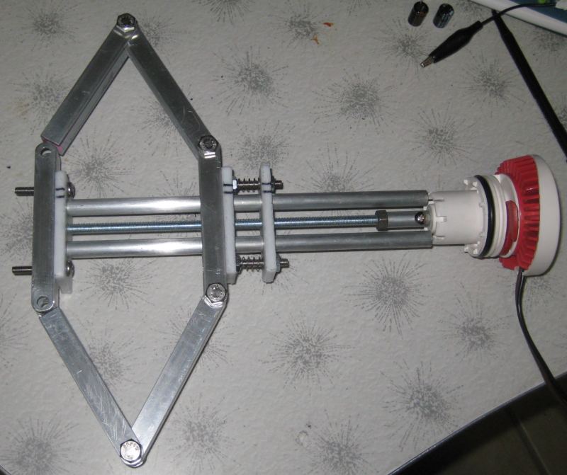
Today we got the manipulator (better known as the claw) finished, and installed. We had a few design issues, such as the motor alignment and the slightly bent threaded rod causing the linear actuator to bind. We solved it by making the motor to threaded rod coupling "float", with a drive pin connecting them together loosely.
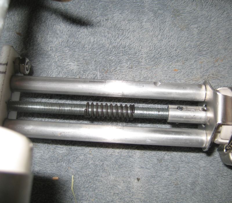
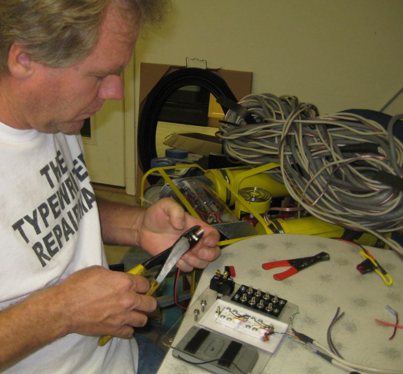
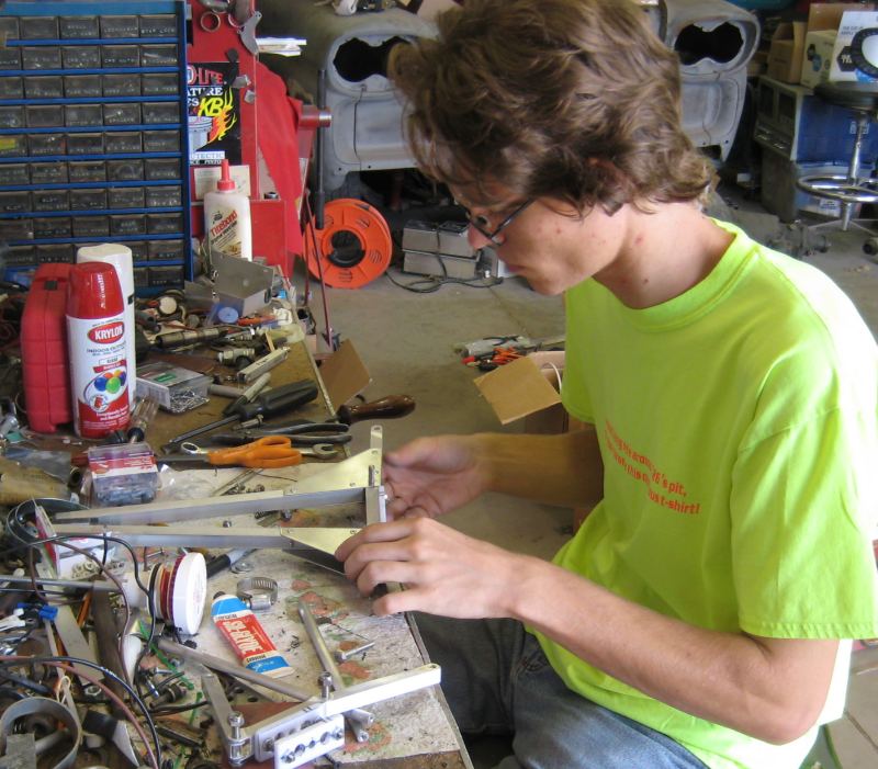
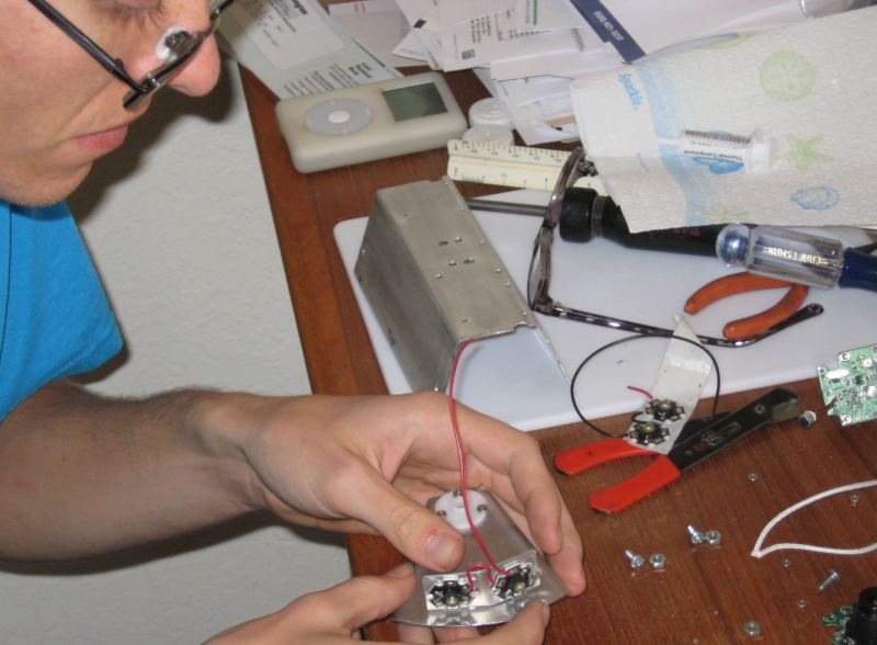
The spring is there to keep it from jamming in the full open
position. Here Steve is working safely fitting parts
and here is our friend notBob with his claw installed, ready for some underwater fun, which you can read about on the testing page.
5/22/2009
We did some minor work to the frame, made the back part a bit wider to match the front, adjusted the angle of the forward thruster nozzles, and added a handle and larger floaty.
The changes to the motor wires seem to have fixed the leak. We had
the ROV in the water for at least an hour, and the SCULL is still dry.
Steve got to drive it around a lot, and we added a stick to the bottom
to simulate a manipulator. We need to get the real one done soon! Also
David finished assembling the spare electronics boards, he's leaving on
a trip tomorrow.
5/21/2009
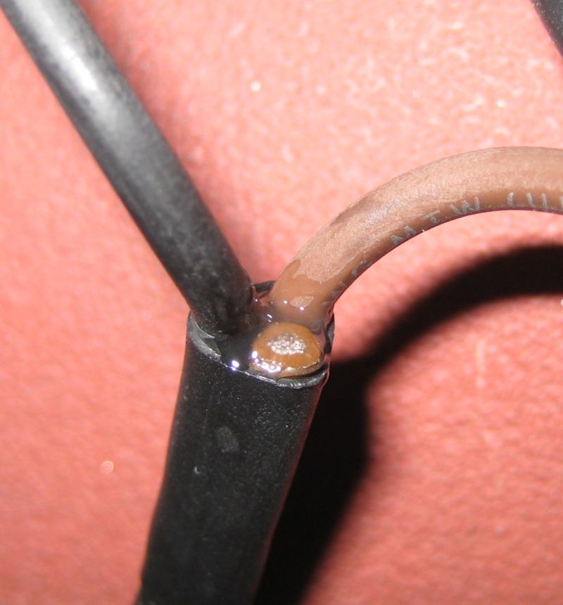
I went to work fixing the motor connectors, sealing them up so they should not be able to leak at all. The main goal is to back up the heat shrink tubing so that it cannot flex inward away from the gland. I got some syringes and epoxy, and after drying the wires with compressed air, I injected the epoxy in each of the three voids.
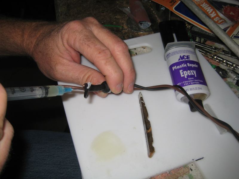
We'll have to wait until after graduation to try them....congrats Gary and Kevin!
5/20/2009
David got the other electronics board built enough to run all the stuff we need (it has the power supply, one motor controller, and the servo stuff done). Steve and I went to Tucson and helped finish the wiring and brought Bob home for more assembly and testing.

Steve did more work on the wiring, and we installed a fan on the
boat to help distribute heat, because the lights get pretty hot.
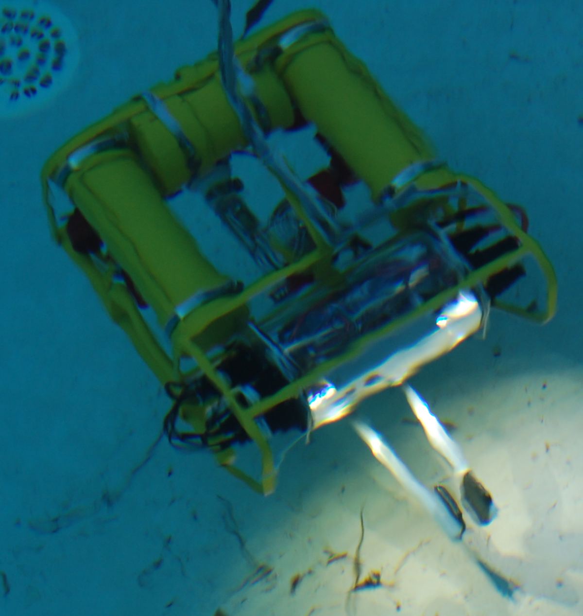
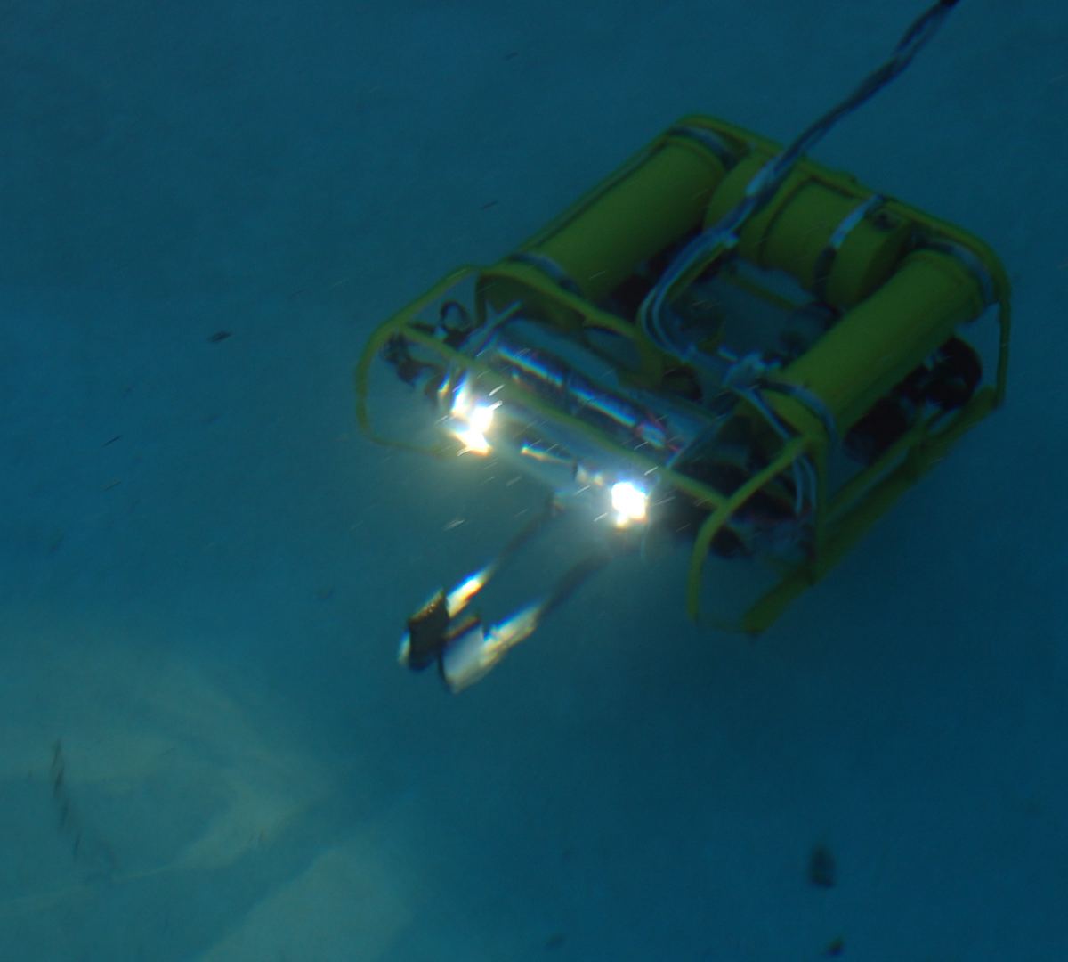
Once it was all ready, we put it in the water for some testing!
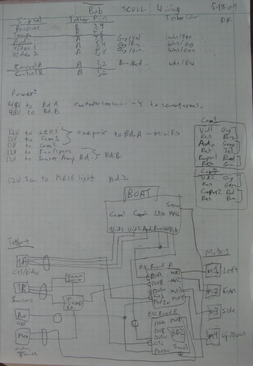
5/18/2009
David got the wiring done. Here's the schematic.
Then he did a bit of water testing in a wading pool.

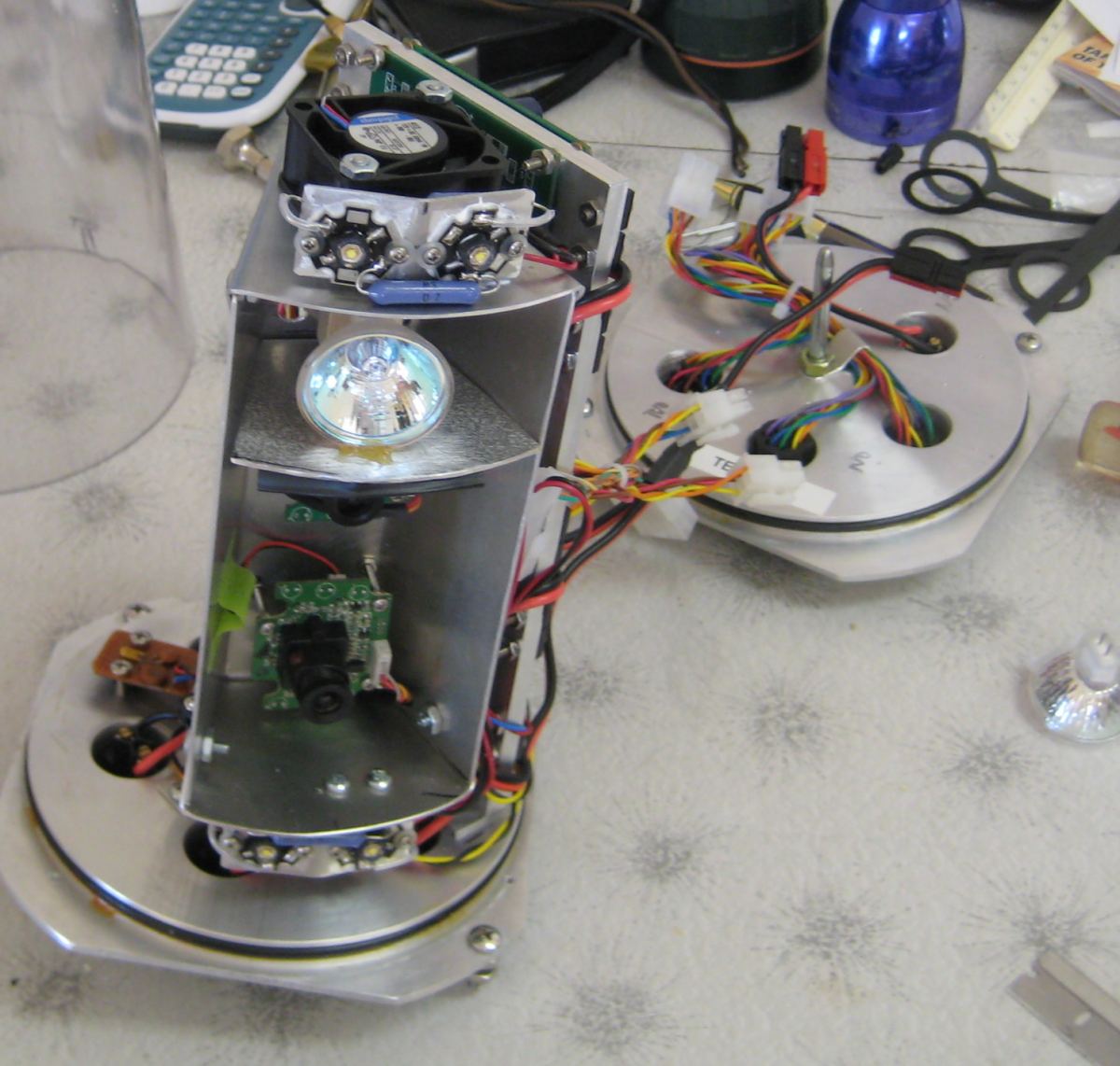
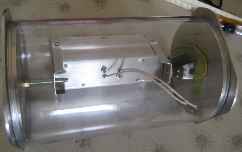
A closer view of the electronics, and the LEDs lit up. The second electronics board is not installed yet, it will power the camera/light boat servo, the halogen light, and the manipulator motor. It will be the same as the first board, and will be mounted to the opposite side of the thick aluminum plate.
There is still more work to do getting it all balanced, floating properly, adding some safety shields, etc. Also the manipulator needs just a bit more work before it can be installed. And we are considering buying more of the Rule pump motors to replace the Attwoods, as they are easier to mount and add shields to.
5/17/2009
Later that day....we worked on the claw some, but it's not done yet. Looks like it might work, there are some bugs to work out.
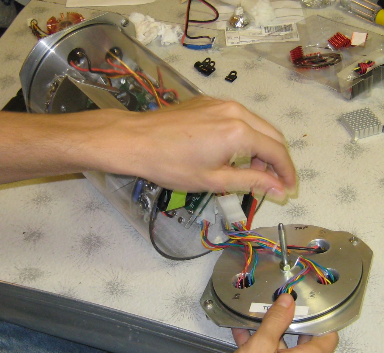
Yesterday Steve and I went to Tucson to visit David, because he called and said he'd have the first electronics board done that afternoon. First we finished mounting the LEDs to the "boat).
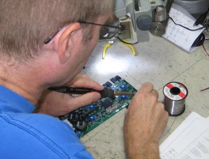
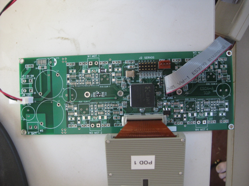
David working on the electronics board, he's pretty good at soldering on surface mount components.
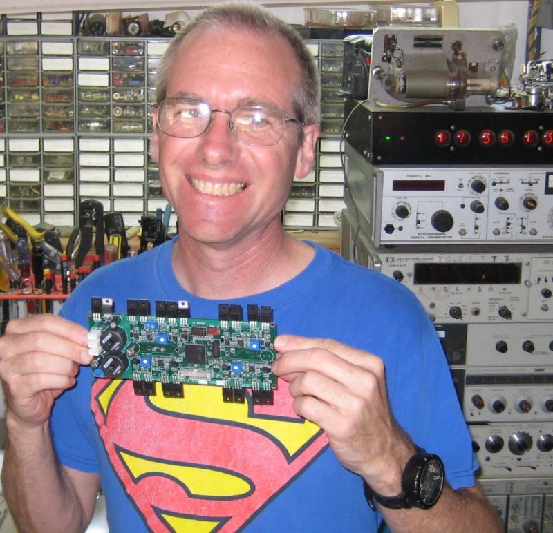
The finished board. Note the modern, sophisticated test equipment below the home brew atomic Nixie clock.
The board mounted into the enclosure, with the motor wires attached to the connectors.

We got the signal wiring about half done by 11 PM and decided to call it a night. Hopefully David will get it wired up and test the motor controllers using the vEx transmitter, driving the four thrusters, in his bathtub... He will also finish up the camera wiring, and test them and the LEDs. If it all works, the plan is to build the other board, which will operate the manipulator motor, the camera servo, and power the switched halogen light.
Meanwhile, Steve and I are working on building the manipulator, as shown in the 3d rendering on the 8th of this month.
5/16/2009
I got the rest of the connectors from David, along with the tether, and Steve and I put it all together, and got it wet. It got wet inside the first time...I think a connector was not fully seated...but it stayed dry after that. We used the same technique of pinching the heat shrink tubing between the two wires to seal the power cable, which is #16 high quality speaker cable, of zipcord construction. We also put a connector on the side thrust motor, and the only connector not yet with a wire in it is the six pin connector that will be used for the manipulator, temperature probe, and whatever else we realize we need later. Here the tether is being temporarily attached before the first water test
5/13/2009
David is making progress on the electronics:
"The PC boards arrived. I soldered down the controller parts and have the logic analyzer and JTAG programmer hooked up and displaying the internal states of the counters. I'm now ready to connect the Vex transmitter to see if the CPLD can decode the PWM signals from it."
5/11/2009
David said the circuit boards for the speed controllers arrived in the mail today, so he can start assembling them as soon as he gets done building a few more Nixie watches for customers. Cathode Corner is sponsoring this project by providing the electronics for notBob.
5/9/2009
Happy Birthday, Steve!
David has been working on the programming of the speed controllers. He also got some smaller glands for the connectors, and I will play with the wires from the motors to see if I can seal them. He got some heat shrink tubing with adhesive inside, and showed me a technique to have two wires enter one end of the tube, and seal the wires individually.
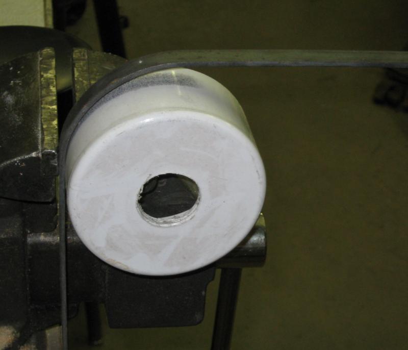
I worked on the thruster mount design, and made one.
5/5/2009
Happy Birthday David!
I worked on connector holes in the servo side end plug yesterday and today, they are done. I put some bolts and an extension cord into the connector housings, and gave the encloser it's first water test...which it failed...but passed just fine after I tightened the connector gland nuts with a wrench, instead of just my fingers.
Then I worked on the frame, making the brackets that hold the SCULL (Sealed Compartment for Underwater Lights and Lectricity), and mounted it. I might try a full frame water test tomorrow...we'll see.
5/3/2009
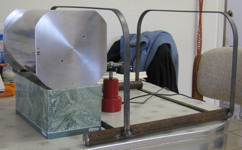
I added some more parts to the frame this morning... I'll work on mounting the electronics enclosure, now that we have the connectors and stuff needed to finish the end plugs. Don't mind the napkin dispenser.
David has been working on the electronics board design, and was ready to order parts for it today. We also milled another 12mm off the edge of the aluminum plate he has to mount the boards on. The test fit indicates it will probably work. I'll work on mounting the plate to the end plug, as he gave me a print of the circuit board design, with notations for the height of some tall components. The plan is to have two boards, one on each side of the moutning plate. One board will power one light, and the four thrust motors, while the other will power the other lights, the manipulator, and the servo.

Steve worked on a logo design for the team.
Janet worked on the first draft of the Technical Report.
5/2/2009
The next morning...added two more parts to the frame, it's getting sturdy.

I enjoy mock ups....they help me see how to do the next step.
5/1/2009
Later that night......I started working on the frame, of 12 x 3 mm steel strap, with 25mm diameter steel skids. I used a fancy bending jig to get the corners just right
and welded the parts together with my MIG welder.
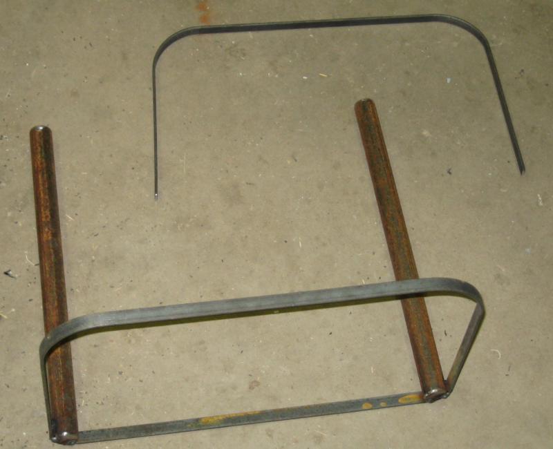
The curves fit the ABS end caps nicely. Still a lot of work to do...but it's getting there!

Also David called and said the board layout for the electronics is going nicely, and he has a piece of aluminum for it to mount on, although it will probably need to be trimmed a bit more (to about 102 x 204 mm). We discussed mounting it, and decided to design some sheet metal corner brackets to connect it solidly to the end plug, so it would not require screw holes through the end plug.
I worked on mounting the end plates of the camera/light boat (as David calls it). The servo is not yet mounted to the end plug, but otherwise it's all done.
I also tested it sort of by putting the reciever and battery from an R/C plane into the enclosure, and moving it. Should be ok....
4/30/2009
I worked on the end parts some more, they are now faced on the outer surface where the connector gaskets will mount, and the one with larger corners has been trimmed to match the other one. I drilled and tapped a hole for the pivot bolt to support the gimbal at one end, and I'm working on setting up the servo mounting at the other end. The glare experiment helps me figure out the clearances needed.
4/27/2009
I did some more work on the gimbal thingy, including making brackets to mount the servo, and attaching the light, cameras, and end plates. It looks nifty!
4/26/2009
later that day: I worked on the gimbal to mount the cameras and lights. Also had the idea that it might be better to mount the LEDs at the ends of the gimbal, and use only two per side, to make mounting the other stuff easier. Here is progress on the gimbal, made of 1.2mm Aluminum sheet, using whatever tools I had in my garage (mostly tin snips and a thick metal work bench and a vise)
David said he would get the parts for the prototype speed controller, and the waterproof connectors, ordered. The connectors are expensive, about $200 for eight, including the cable and bulkhead ends of each. It's probably money well spent, if they work ok, considering how difficult sealing cables is.
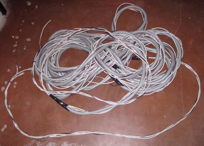
David worked on the tether, purchasing some 19mm diameter foam "backer rod" from a home building supply store, and weaving the three tether cables and the foam into a floating tether.
4/25/2009
I finished the second end plug yesterday. Steve worked on some Soldidworks design of the robot. Today we had a meeting, David, Steve and Jim, at David's house. We discussed the electronics system, and figured out how the electronics enclosure could be layed out. Steve worked on putting the new information into Solidworks. We bought a servo to mount the cameras and light, and some cable for the tether-a 50m Cat 5e Ethernet cable, and 30m 16 gage speaker wire.

We cut the polycarbonate tube to length, using a miter box that David made for another project. The length depended on several things, including the size of the servo, the size of the electronics board, LEDs, and the electrical connectors. After all this, it was decided to make it as long as the first guess I made back in the beginning of March!
4/24/2009
The parts for the electronics enclosure arrived while we were in Atlanta. The polycarbonate tube doesn't look as nice as I hoped it would, there are wavy lines along it. It also is not as big as it should be, it's about 1mm smaller in diameter than specified. Even so, it should work fine, as testing has shown, but first things first. The end plugs are to be made of 12.7mm thick aluminum plate, cut to square size then turned on the lathe. I made one of them, using my antique South Bend lathe.
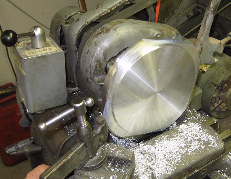
This is before turning the groove for the O ring.
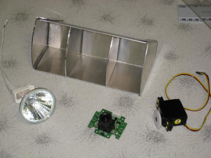
I also started working on a Bill of Materials, we need to hurry up and order some parts.
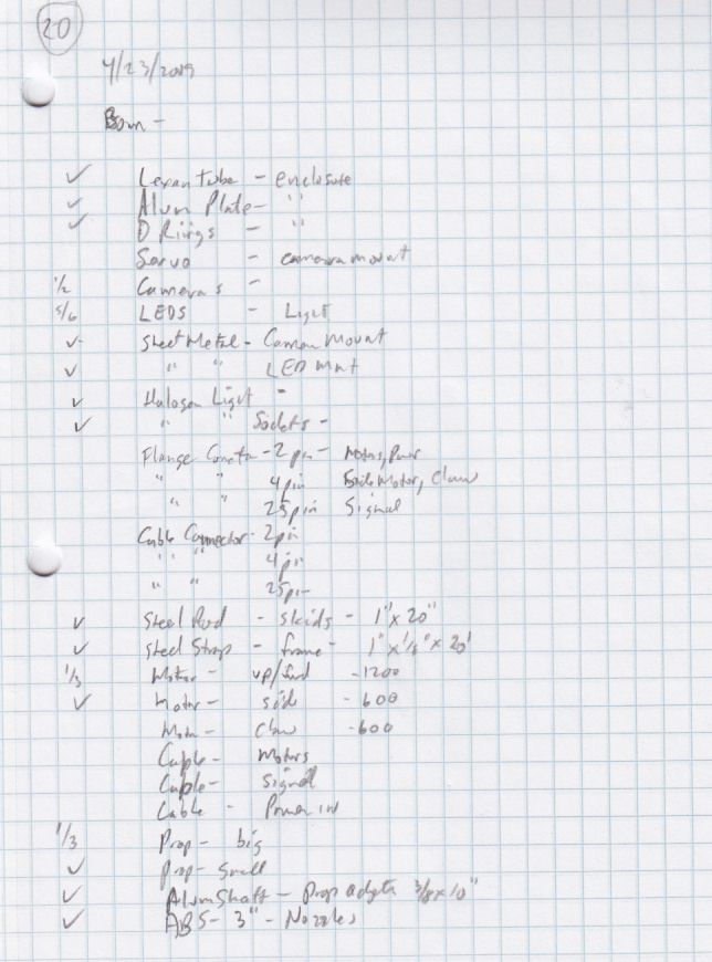
4/13/2009
I ordered the parts for the electronics enclosure, a 0.6m long polycarbonate tube, a strip of 13mm thick aluminum the same width as the OD of the tube, and some O rings to fit inside the tube. I also bought some steel locally, three 2m long pieces of strap 25mm x 3mm, and a round bar 1.3m long by 25mm diameter.